


What is an Amplifier? What Amplifier Do? Introduction of Amplifier
Amplifiers are fundamental electronic devices designed to increase the amplitude of a signal. As a respected player in the audio amplification industry, Jazz Hipster is committed to staying at the forefront of technological advancements in this field. Our team of experienced engineers consistently works to enhance audio amplification capabilities, drawing on our deep understanding of both traditional and emerging new technologies.
We recognize that the selection of an appropriate amplifier topology and class is a critical decision in audio system design, profoundly influencing overall performance, efficiency, and cost-effectiveness. Our modular approach to amplifier design allows for efficient customization to meet specific ODM requirements.
In this article, we will explore the fundamental concepts of amplifiers, various types and classifications, and the principles behind their operation. By understanding these elements, you’ll gain insight into how Jazz Hipster’s solutions contribute to the advancement of audio amplification technology.
Types of Amplifiers

Classification based on amplifier class
In the realm of audio amplification, the class of an amplifier fundamentally defines its operational characteristics, efficiency, and audio quality. These classifications are crucial for audio engineers and system designers when selecting the optimal solution for a given application.
Class A Amplifiers
Class A amplifiers are renowned for their exceptional linearity and audio fidelity, consistently operating across the entire signal cycle to avoid crossover distortion. However, this continuous operation leads to relatively low efficiency. The average efficiency of a Class A amplifier can vary widely depending on the specific design and operating conditions, typically ranging from about 10% to 20%. Advanced techniques, such as inductive biasing, may improve efficiency, but the actual improvement can be less common and significant in practical scenarios.
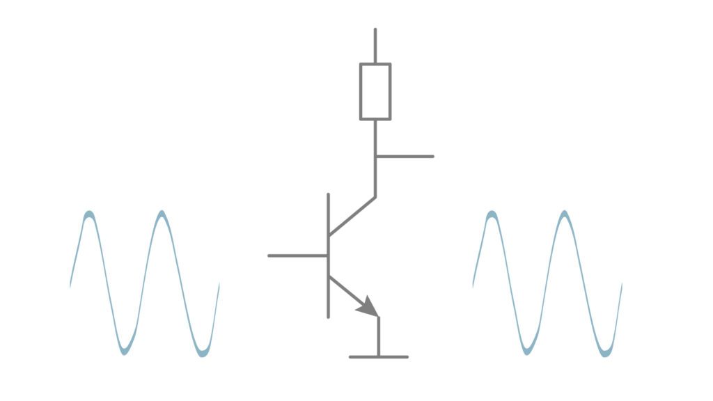
Class A audio amplifiers, recognized for their superior linearity, suffer from lower efficiency.
The constant current flow in Class A designs necessitates careful thermal management, as these amplifiers dissipate significant power even in the absence of an input signal. Despite their relatively low efficiency, Class A amplifiers remain the gold standard for applications where audio quality is paramount, such as high-end preamplifiers and audiophile-grade power amplifiers.
Class B Amplifiers
Moving towards improved efficiency, Class B amplifiers employ a push-pull configuration where each active device conducts for precisely half of the signal cycle. This design significantly reduces power consumption during idle periods, resulting in improved efficiency compared to Class A. The efficiency of Class B amplifiers can vary considerably based on the specific implementation and operating conditions. In theory, Class B amplifiers can achieve efficiencies up to 78.5% (π/4) under ideal conditions. However, in practical applications, the actual efficiency often ranges from about 50% to 60%, depending on factors such as signal level, load impedance, and circuit design.
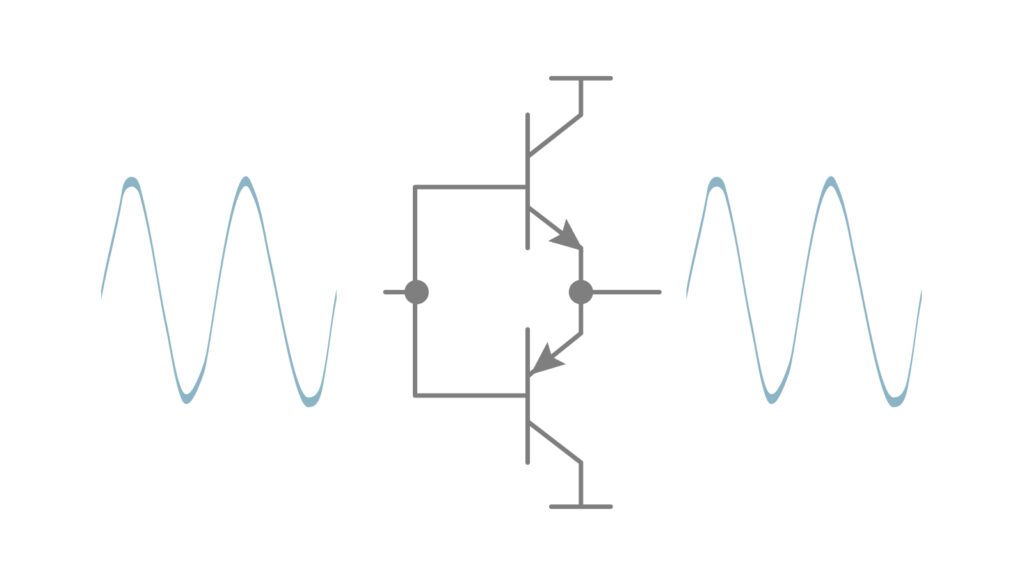
Class B audio amplifiers operate by activating the output transistors only during one half of the signal’s cycle. To fully amplify the signal, it utilizes a pair of transistors, with one handling the positive and the other the negative outputs.
However, the transition between the positive and negative half-cycles introduces the potential for crossover distortion, particularly at low signal levels. Mitigating this distortion requires precise matching of complementary devices and sophisticated thermal compensation techniques. Class B amplifiers find their niche in applications where efficiency takes precedence over absolute signal purity, such as in medium to high-power audio systems and certain RF power amplifiers.
Class AB Amplifiers
Class AB amplifiers represent an elegant compromise between the linearity of Class A and the efficiency of Class B designs. By maintaining a small bias current, Class AB amplifiers ensure that both devices in a push-pull configuration remain partially conductive near the zero-crossing point, significantly reducing crossover distortion.
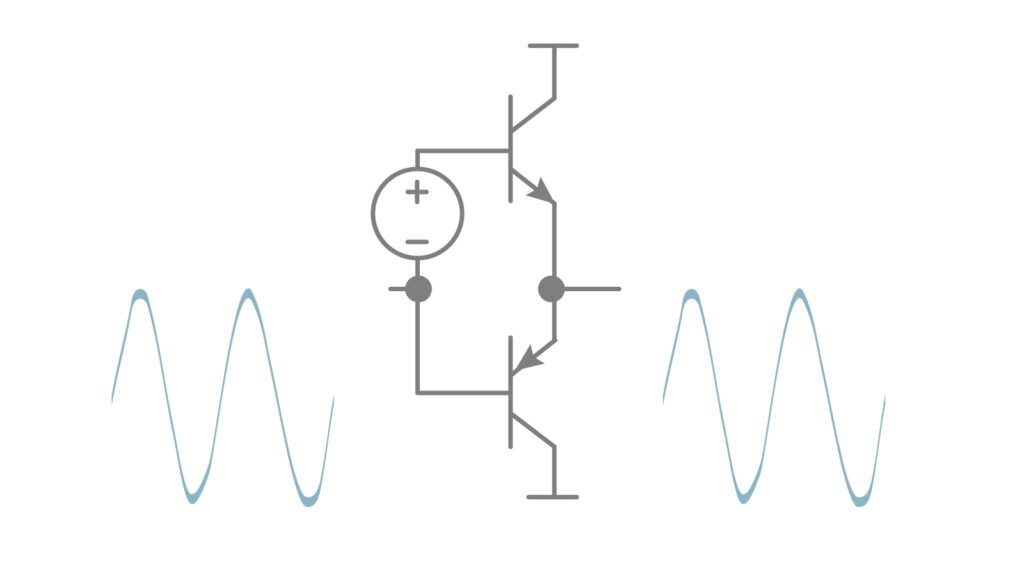
Class AB amplifiers are designed to have their transistors slightly biased to conduct at the signal’s near-zero transitions. This configuration results in greater efficiency than Class A amplifiers and lower distortion than Class B amplifiers.
Class AB amplifiers offer a balanced solution for a wide range of audio applications. The design of these amplifiers requires careful consideration of the optimal bias point to balance efficiency and linearity, often incorporating sophisticated bias stabilization circuits to maintain consistent performance across varying thermal conditions.
Class D Amplifiers
Class D amplifiers, often referred to as switching amplifiers, operate on a fundamentally different principle compared to their linear counterparts. These amplifiers utilize pulse-width modulation (PWM) to create a high-frequency switching output, which is subsequently filtered to recover the amplified audio signal.
Class D amplifiers achieve high efficiency through a switching technique that toggles the output devices between fully on and fully off states, avoiding the linear region where power loss is greater. Under optimal conditions, particularly at higher power outputs and with suitable load impedance, modern Class D amplifiers can achieve efficiencies up to 90% or higher. However, it’s important to note that actual efficiency can vary significantly depending on the specific design, operating conditions, and output power level.
While this high efficiency is a significant advantage, it introduces challenges such as out-of-band noise and electromagnetic interference (EMI). The audio fidelity of Class D amplifiers heavily depends on the modulation technique and the precision of the output filtering process, which must effectively remove high-frequency switching artifacts to preserve sound quality. This high efficiency translates to minimal heat dissipation, allowing for compact designs and reduced cooling requirements. However, the implementation of Class D topology presents unique challenges, including complex modulation and demodulation circuitry, critical output filter design, and the need for careful PCB layout to minimize EMI. These challenges must be addressed to ensure that the amplifier delivers not only high efficiency but also maintains excellent audio quality.
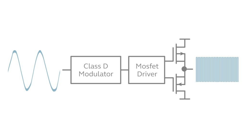
Class D audio amplifiers utilize a high-frequency switching output that surpasses the highest frequency of the audio signal needing reproduction. The efficiency of these amplifiers is increased because their output transistors switch between fully on and fully off states during operation.
Advanced Class D designs incorporate feedback and error correction techniques to improve linearity and reduce distortion, allowing these amplifiers to achieve audio performance that rivals traditional linear designs while maintaining their efficiency advantage.
Class G and Class H Amplifiers
For applications demanding both high efficiency and premium audio quality, Class G and Class H amplifiers offer advanced topologies that build upon the foundation of Class AB design.
Class G amplifiers employ multiple power supply rails, dynamically switching between voltage levels based on the instantaneous signal amplitude. This approach significantly improves efficiency, particularly at lower power levels, while maintaining the linear operation characteristics of Class AB.
Class H amplifiers take this concept further by implementing a modulated power supply that continuously tracks the audio signal. By minimizing the voltage drop across the output devices, Class H designs achieve even greater efficiency improvements across the entire operating range.
These advanced amplifier classes exemplify the ongoing innovation in audio amplification technology, pushing the boundaries of what’s possible in terms of both efficiency and audio fidelity.
How Amplifier Works? Principle of Amplifier Operation
A. Gain (voltage, current, power gain)
The fundamental purpose of an amplifier is to increase the magnitude of an input signal, a concept quantified as gain. In audio amplification, gain is typically expressed in three forms: voltage gain, current gain, and power gain. Each of these metrics provides crucial insight into an amplifier’s performance characteristics and suitability for specific applications.
Voltage Gain (Av) is defined as the ratio of output voltage to input voltage. In many audio applications, particularly in the realm of small-signal amplification, voltage gain is a primary consideration. It is often expressed in decibels (dB) to accommodate the wide range of gain values encountered in practical circuits:
Current Gain (Ai) represents the ratio of output current to input current. While less commonly emphasized in audio applications, current gain becomes a critical factor in designs interfacing with low-impedance loads or in current-driven circuits:
Power Gain (Ap) is perhaps the most comprehensive measure of amplification, representing the ratio of output power to input power. In audio power amplifiers, where the ultimate goal is to drive loudspeakers efficiently, power gain is a key performance indicator:
It’s worth noting that in many practical amplifier designs, these gains are interdependent and influenced by factors such as input and output impedances, frequency response, and the specific topology employed.
B. Ideal Amplifier Characteristics
While practical amplifiers invariably deviate from perfection, understanding the characteristics of an ideal amplifier provides a benchmark against which real-world designs can be evaluated:
- Infinite Input Impedance: An ideal amplifier would present an infinite impedance to its input signal source, ensuring that it does not load or affect the source in any way.
- Zero Output Impedance: Conversely, an ideal amplifier would have zero output impedance, capable of delivering any required current to the load without voltage drop.
- Flat Frequency Response: The gain of an ideal amplifier would remain constant across a wide range of frequencies, from DC to high frequencies.
- Zero Noise: An ideal amplifier would introduce minimal noise to the signal, preserving the signal-to-noise ratio of the input.
- Infinite Bandwidth: Related to flat frequency response, an ideal amplifier would operate effectively at all frequencies.
- Perfect Linearity: The output of an ideal amplifier would be a perfect, scaled replica of the input, free from any distortion.
In addition to these standard characteristics, some advanced discussions of ideal amplifiers also include:
- Infinite Slew Rate: An ideal amplifier would be capable of instantaneous changes in output voltage, regardless of the rate of change of the input signal. Though practical amplifiers have limitations, understanding slew rate is crucial for high-frequency applications as it can significantly impact dynamic performance.
In practice, amplifier design involves a series of carefully considered trade-offs among these ideals. For instance, achieving a wider bandwidth often comes at the cost of increased noise, while pursuing higher power output may necessitate compromises in linearity. Understanding these principles and ideal characteristics, including less commonly discussed ones like slew rate, is crucial for audio engineers and designers in evaluating and optimizing amplifier performance across a wide range of applications.
Amplifier Configurations
A. Common Emitter Amplifiers
The common emitter (CE) configuration is a fundamental topology in bipolar junction transistor (BJT) amplifier design, widely utilized in audio applications due to its versatility and performance characteristics. In this configuration, the emitter terminal serves as the common point for both input and output signals, while the input is applied to the base and the output is taken from the collector.
Key attributes of the common emitter configuration include:
- High Voltage Gain: CE amplifiers can offer a wide range of voltage gains, typically from about 10 to 200 for a single stage, depending on the specific design and operating conditions. Multi-stage designs can achieve higher gains. The actual gain in a practical application will depend on factors such as the transistor characteristics, biasing, and load conditions. This versatility makes CE amplifiers suitable for a wide range of audio applications.
- Moderate Input Impedance: The input impedance of a CE stage is generally in the kilohm range, offering a good compromise between signal source loading and gain.
- Moderate Output Impedance: CE amplifiers present an output impedance in the range of several kilohms, which can be further optimized through negative feedback techniques.
- 180-Degree Phase Shift: The CE configuration inverts the signal, introducing a 180-degree phase shift between input and output. This is often used in multi-stage amplifier designs for phase correction.
- Bandwidth Considerations: The high-frequency response of CE amplifiers is limited by the Miller effect, where the base-collector capacitance is effectively multiplied by the voltage gain. Various compensation techniques, such as cascode configurations or Miller capacitance neutralization, are employed to extend high-frequency performance.
In audio applications, CE stages are often cascaded to achieve high overall gain while maintaining controlled frequency response. The inherent non-linearity of BJTs in this configuration necessitates careful biasing and often the application of negative feedback to achieve the desired level of distortion performance.
B. Bridged Amplifier Configuration
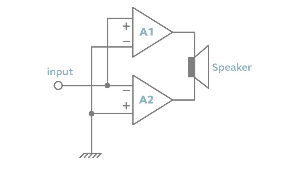
The bridged amplifier configuration, also known as the bridge-tied load (BTL) or H-bridge configuration, integrates two amplifier channels to drive a single load, significantly increasing the output capability. This topology offers several notable advantages:
- Increased Voltage Swing: By utilizing both the positive and negative swings of two out-of-phase amplifier outputs, the bridged configuration increases the potential voltage swing across the load. This can significantly increase power output capability. Under ideal conditions, with a purely resistive load and assuming the amplifier can swing to the full supply rails, it can theoretically quadruple the power output for a given supply voltage compared to a single-ended configuration. However, in practice, the actual increase in power output may be less due to factors such as amplifier limitations, load characteristics, and thermal considerations. Typically, a bridged configuration might realistically achieve a 2.5 to 3.5 times increase in power output compared to a single-ended design.
- Improved Damping Factor: The effective output impedance of a bridged amplifier is reduced, leading to an improved damping factor. This enhanced electrical control over the loudspeaker can result in tighter bass response and overall improved transient behavior.
- Ground-Independent Operation: Since the load is connected between two active outputs rather than between an output and ground, the bridged configuration offers improved immunity to ground-loop issues and can simplify system integration in some cases, depending on the specific application and setup.
- Enhanced Efficiency: For a given power output, the bridged configuration can allow for lower supply voltages, which may improve overall system efficiency. This is particularly relevant in Class D implementations, although the degree of improvement can vary depending on the specific design and conditions.
However, the bridged configuration also presents certain challenges:
- Increased Complexity: The need for two amplifier channels and precise phase management increases circuit complexity and cost.
- Potential for Instability: The interaction between the two amplifier channels can lead to stability issues, necessitating careful design and optimization of feedback and compensation networks to maintain stable operation.
- Load Considerations: Bridged amplifiers typically require floating (ungrounded) loads, which may limit compatibility with some speaker systems or necessitate the use of output transformers in certain applications.
In professional audio and high-power consumer applications, bridged amplifiers are often employed to achieve maximum power output from a given amplifier chassis size. The technique is particularly effective when combined with switch-mode power supplies and Class D output stages, enabling remarkably compact yet powerful amplification solutions.
The implementation of bridged amplifiers requires careful attention to phase matching, DC offset control, and protection circuitry to prevent damage in case of output short circuits. Advanced designs may incorporate adaptive bridging, where the amplifier can switch between bridged and single-ended modes based on load conditions or power requirements, offering a flexible solution for varying application demands.
Amplifier Configurations
Throughout this article, we’ve explored the world of audio amplifiers, examining various classes and configurations. We’ve seen how different amplifier designs offer unique trade-offs between efficiency, linearity, and power output, each suited to specific application requirements. The field of audio amplification continues to evolve, with emerging technologies opening new possibilities for performance improvement and innovation.
At Jazz Hipster, we are dedicated to contributing to this advancement through our focus on customizable solutions that blend proven techniques with innovative approaches, helping our clients to create high-quality products. As the audio landscape continues to change, we are committed to adapting and innovating to meet the evolving challenges in audio amplification.
References
- [1] AB类放大器工作原理、偏置方法及功率计算公式-IC先生 – https://www.mrchip.cn/newsDetail/593
- [2] Amplifier figures of merit – https://en.wikipedia.org/wiki/Amplifier_figures_of_merit
- [3] Analog Device – https://www.analog.com/cn/index.html
- [4] MIT OpenCourseWare – https://ocw.mit.edu/courses/6-012-microelectronic-devices-and-circuits-fall-2009/18a2d9a52234f9e962d74b5599759767_MIT6_012F09_lec18.pdf
