
The fundamental operating principle of a speaker driver is simple: when an alternating current signal flows through the voice coil, it generates a fluctuating magnetic field. This field interacts with the magnetic field in the motor system’s magnetic gap, producing a repelling force that drives the voice coil and diaphragm, causing air vibrations that generate sound. While this principle is straightforward, the actual movement of the driver involves numerous complex nonlinear phenomena that result in distortion.
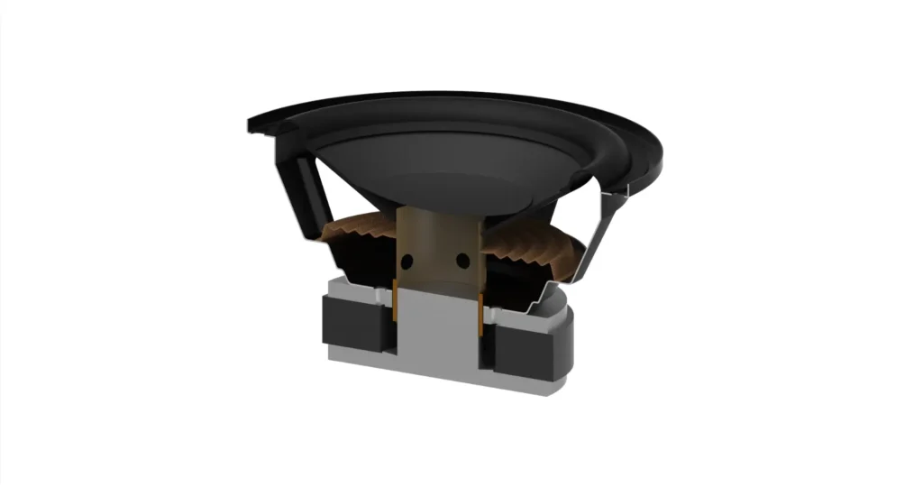
To understand the causes of these distortions and their corresponding mitigation methods, let’s first review the basic structure of a conventional speaker driver motor system. The diagram below illustrates the cross-section of a typical woofer motor system:
BL(x) Nonlinearity
The primary sources of distortion in a speaker driver are related to the position (x) of the voice coil within the magnetic gap during its motion.
By simulating this structure in FEA software, we can obtain a magnetic field intensity distribution map:
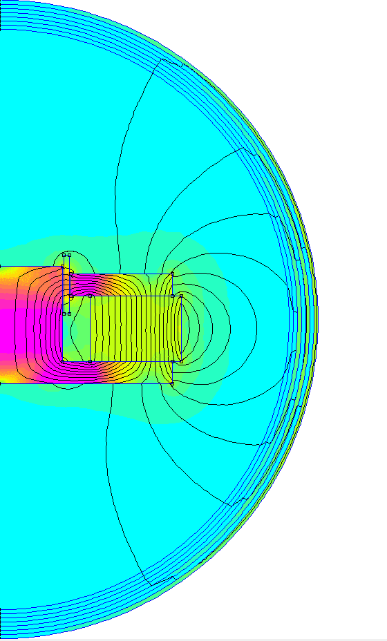
As shown in the figure, the magnetic field distribution within the gap is not uniform. This causes the force factor BL value to change continuously as the voice coil moves, forming the nonlinear characteristic BL(x). Since the force driving the voice coil and diaphragm is based on BL(x), this nonlinear force leads to harmonic distortion and intermodulation distortion in the sound.
Below is an example of a BL(x) curve:
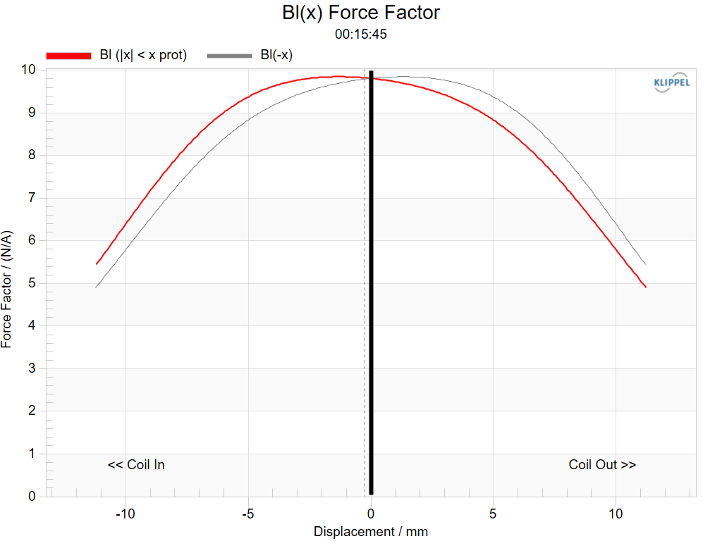
There are several ways to make BL(x) more linear and symmetric. Common approaches include modifying the shape of the T-yoke and pole tip or using an undercut pole tip to create a more uniform magnetic field distribution in the gap. Although undercut designs help achieve better BL(x) symmetry, they often reduce the magnetic field strength in the gap, lowering the driver’s sensitivity. This requires compensatory adjustments, such as increasing the magnet size or altering other aspects of the motor structure.
In some cases, simply adjusting the initial position of the voice coil during assembly can improve BL(x) symmetry. Some drivers use an underhung magnetic gap design (short voice coil in a long gap) to ensure the coil operates within a more linear magnetic field range. However, this design may limit the maximum power handling and excursion capability of the driver. Another less common but effective approach is using radially magnetized magnets to create a uniform radial magnetic field for the voice coil to move within, although this method comes with higher costs and assembly complexity.
Kms(x) Nonlinearity
Due to their inherent shapes, the surround and suspension of a speaker driver often exhibit mechanical properties that are neither symmetric nor linear. For example, in a typical half-roll surround, the material stretches outward when moving outward, while it first curls inward before fully compressing when moving inward. This causes the restoring force applied to the moving assembly to be inconsistent. The suspension exhibits similar behavior, leading to another common nonlinear characteristic known as Kms(x).
Below is an example of a Kms(x) curve:
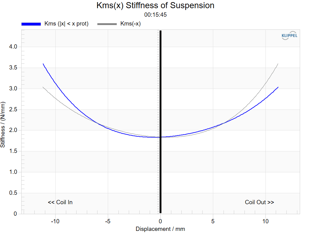
Beyond contributing to harmonic distortion, the most troublesome effect of Kms(x) nonlinearity is the creation of DC offset, where the resting position of the voice coil shifts toward the direction where the surround and suspension exert weaker restoring forces. This exacerbates other nonlinear electromagnetic distortions.
To improve Kms(x), the primary solutions involve adjusting the shape of the surround and suspension, or using a dual-mirror suspension assembly to cancel out nonlinear characteristics. However, blindly striving for a perfectly linear Kms(x) is not advisable, as the suspension must provide adequate restoring force within the excursion range to control the maximum movement of the voice coil, ensuring it does not exit the magnetic gap and cause mechanical failure.
Le(x) Nonlinearity
The voice coil itself functions as an air-core inductor with its own inductance value. When a ferromagnetic core is inserted into an air-core inductor, its inductance increases, and when removed, the inductance decreases. A similar phenomenon occurs as the voice coil moves, as the shape and total volume of the surrounding ferromagnetic materials are constantly changing. This results in a varying inductance, known as the nonlinear characteristic Le(x).
Below is an example of an Le(x) curve:
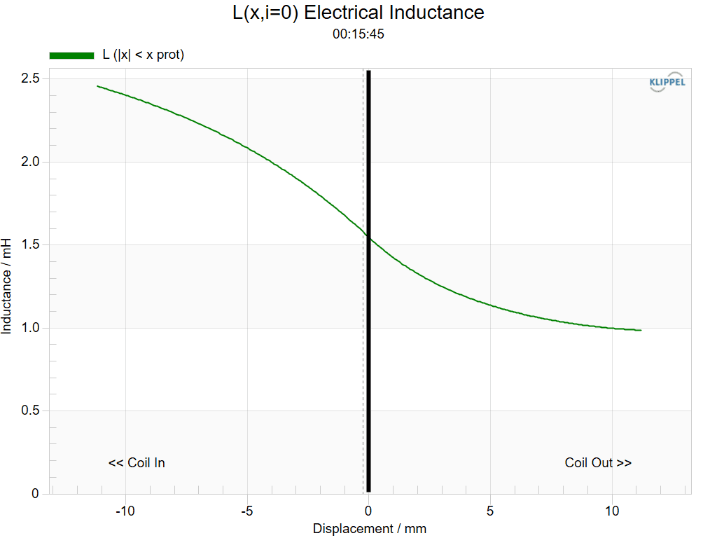
In most drivers, Le directly affects the mid-to-high-frequency response. The nonlinear behavior of Le(x) and BL(x) introduces significant intermodulation distortion in these frequency ranges.
The most effective way to mitigate Le(x) nonlinearity is by incorporating demodulation components in the motor system, such as a copper cap over the pole piece or an aluminum shorting ring. These components generate their own magnetic field in response to changes in the voice coil’s magnetic field, partially canceling out and stabilizing the inductance variations.
The thickness, volume, and positioning of these components are critical to their demodulation effectiveness and must be carefully designed. While a copper cap is highly effective in reducing high-frequency inductance variations, it also increases the magnetic gap width. A wider gap weakens the magnetic field strength, reducing the driver’s sensitivity, requiring appropriate trade-offs in the design.
Conclusion
The three primary sources of nonlinear distortion in speaker drivers each have corresponding solutions. However, achieving an optimal design requires precise FEA simulations and prototype testing.
Jazz Hipster’s experienced R&D team utilizes advanced Comsol and a suite of Loudsoft electroacoustic simulation tools to analyze every detail of speaker components. These designs are further validated using Klippel measurement systems, enabling iterative improvements to help you develop the best-performing driver while meeting cost constraints.
