
In frequency response measurements of loudspeaker systems, the low-frequency region is often the most difficult to measure accurately. In typical indoor measurements, room reflections and room modes prevent simple acquisition of the loudspeaker’s anechoic direct sound.
One common workaround is using the windowing function in measurement software, which narrows the time domain range of the impulse response used for FFT to before the arrival of the first reflection, thereby removing its effect. However, the frequency resolution of this method depends on the window length, meaning the distance from the speaker to the nearest wall or floor determines the lowest usable frequency. Due to the limited size of most indoor spaces, this method typically yields accurate mid- to high-frequency responses only.
Some professional audio brands build gigantic measurement rooms (with dimensions over ten meters in each direction) and suspend the loudspeaker in the centre of the space to maximise the window length, enabling full-range anechoic measurements down to 20 Hz.
The Anechoic Chamber Method

Another, more common method is to use an anechoic chamber. However, anechoic chambers are not perfect. Like normal rooms, they have room modes, though these are significantly dampened by absorptive materials. To obtain accurate low-frequency responses unaffected by room modes, the absorbers must be large enough. The chamber’s usable low-frequency limit depends on the length of its absorbing wedges. The following formula can be used to estimate that limit:
Where f is the lower limit frequency, c is the speed of sound, and L is the length of the absorber.
To achieve a truly anechoic response down to 20 Hz, the absorbers must be around 4.25 meters long. Considering that all six surfaces of the room need treatment, plus additional space for placing the loudspeaker, allowing technician movement, and ensuring the microphone isn’t too close to absorbers, an anechoic chamber capable of full-range measurements typically needs dimensions exceeding 10 meters in all directions. Due to the high cost of such construction, few chambers in the industry meet these specifications.
The Near-Field Measurement Method
Principle and Frequency Limitations
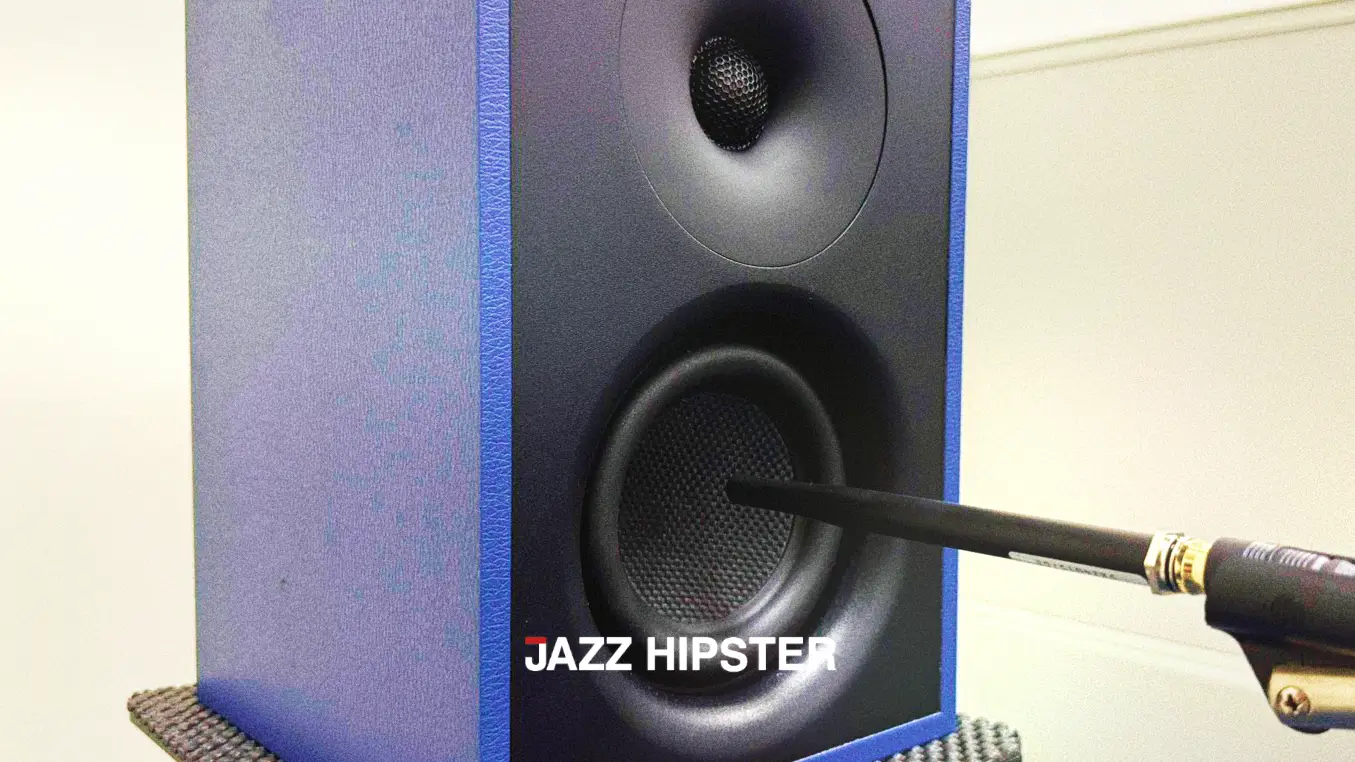
To circumvent the spatial limitations of the above methods for low-frequency measurements, the most common and straightforward approach is near-field measurement.
In the low-frequency range, a dynamic speaker driver behaves like a rigid piston. Under this condition, the near-field response is equivalent to the far-field response. By placing the measurement microphone extremely close to the diaphragm (within 0.11 times the diaphragm diameter), the proportion of direct sound is maximised, producing low-frequency data that is essentially unaffected by room reflections and room modes.
However, near-field measurements have an upper frequency limit. As the wavelength becomes comparable to or shorter than the diaphragm size, or if cone breakup occurs, acoustic interference effects differ between near- and far-field, and the near-field response no longer accurately represents far-field behaviour. The following formula can be used to estimate the upper frequency limit (Fmax) for a flush-mounted driver:
Where D is the driver diameter in inches.
Measuring Bass-Reflex Enclosures
When measuring the low-frequency output of a bass-reflex port, a similar near-field approach can be applied. By summing the near-field responses of the woofer and the port, one can obtain the system’s overall low-frequency response.
Many people adjust the port response level based on its opening diameter before summing. However, this method is prone to errors—especially with flared or low-turbulence port designs—because it’s difficult to determine the effective acoustic diameter for accurate correction.
Here’s a useful tip: when simulating a bass-reflex box in loudspeaker modelling software (such as VituixCAD), if you extend the frequency display to very low frequencies, you’ll notice the woofer’s and port’s outputs overlap at extremely low frequencies. This is because, below the tuning frequency and approaching DC, the rear wave of the woofer effectively “doesn’t see” the enclosure, and the sound pressure output from the port equals the front output of the woofer. So, by starting the near-field measurement from a very low frequency (e.g., 10 Hz) and adjusting the port response level to match the tail of the woofer’s response curve before summing, an accurate system low-frequency response can be obtained.
Response Splicing and the Baffle Step Phenomenon
It is standard practice to merge the near-field response with data obtained via windowing or in an anechoic chamber to get a complete system response. However, this method only applies to 2π conditions (e.g., in-wall or flush-mounted speaker measurements).
For free-field bookshelf or floorstanding speakers, this merging method becomes inaccurate. Near-field measurements don’t capture the baffle step phenomenon, and the measurement environment’s low-frequency limit is often higher than the baffle step frequency. As a result, the combined response may show more low-frequency energy than the speaker actually radiates. Only when the room’s frequency floor is low enough to allow merging at a suitably low frequency can accurate results be achieved.
The Outdoor Ground-Plane Measurement Method
If you want to directly measure the full low-frequency response and baffle step, take the speaker outdoors to an open space. Mount it on a stand, and place the measurement microphone flat on the ground. Then tilt and fix the speaker and stand so that the on-axis direction points directly at the microphone.
For best results, the speaker-to-microphone distance should be 2 meters, which simplifies later calculations. For large floorstanders with multiple woofers, a 4-meter distance may be used to ensure the measurement position is in the far field. In this setup, the ground mirror effect produces a 6 dB gain, which is cancelled out by the 6 dB attenuation due to the 2-meter distance, yielding a response essentially equivalent to a 1-meter full-range anechoic measurement. At 4 meters, you’ll need to compensate the result by +6 dB.
Note that since the microphone isn’t positioned at the “mirror plane” (i.e., not directly on the ground), its distance from the ground will cause some errors at higher frequencies—typically above 9 kHz. Also, outdoor measurements are highly susceptible to background noise and wind, so caution and careful judgment are required to obtain accurate results.
While accurately measuring a loudspeaker’s low-frequency response presents significant challenges, the experienced R&D team at Jazz Hipster excels at overcoming these issues through sophisticated measurement techniques.
We leverage advanced electro-acoustic simulation software for predictive analysis and conduct final validation with high-precision measurement systems. We empower you to obtain the most accurate data amidst complex acoustic problems, ensuring your loudspeaker systems are engineered for exceptional performance from the outset, ready to meet any challenge.